
MARB HandBench: Some Assembly Required
Testing whether AI can put the pieces together
Sunnyday Technologies · September 19, 2026 · Initial results, unranked
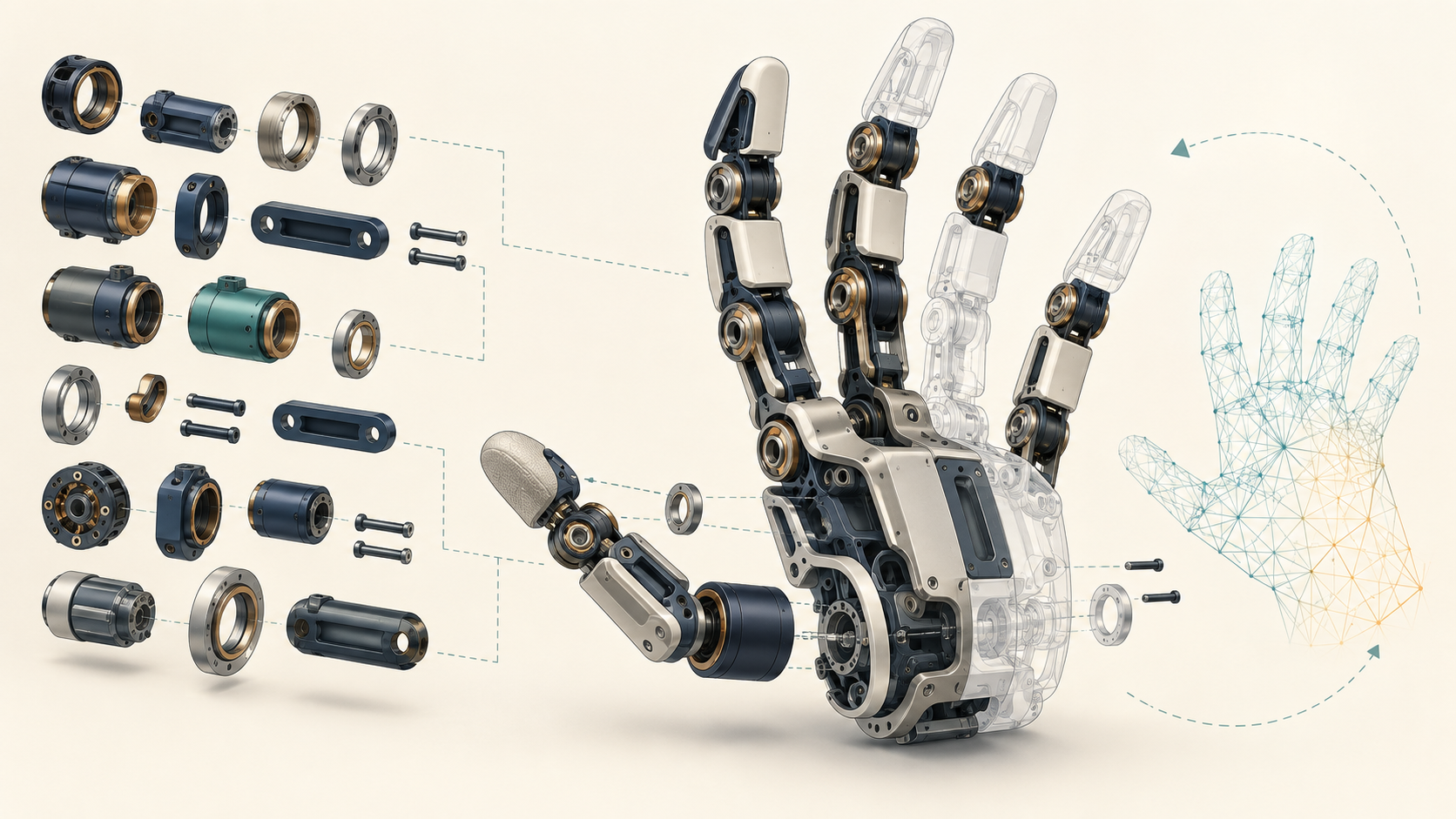
One Grok Bot run returned all 226 required parts of a robot hand. Only one matched the target placement: the part used to align the comparison.
Astra Medium matched 12 placements; Extra high matched 20. The scores are low, which makes this a useful starting point. Sunnyday Technologies' MARB HandBench establishes a baseline for measuring improvement after model and tool updates.
Why a hand?
Holding a mug, picking up a washer and turning a key require different movements. A robot hand must produce them through joints, links, tendons or flexible elements packed into a small space.
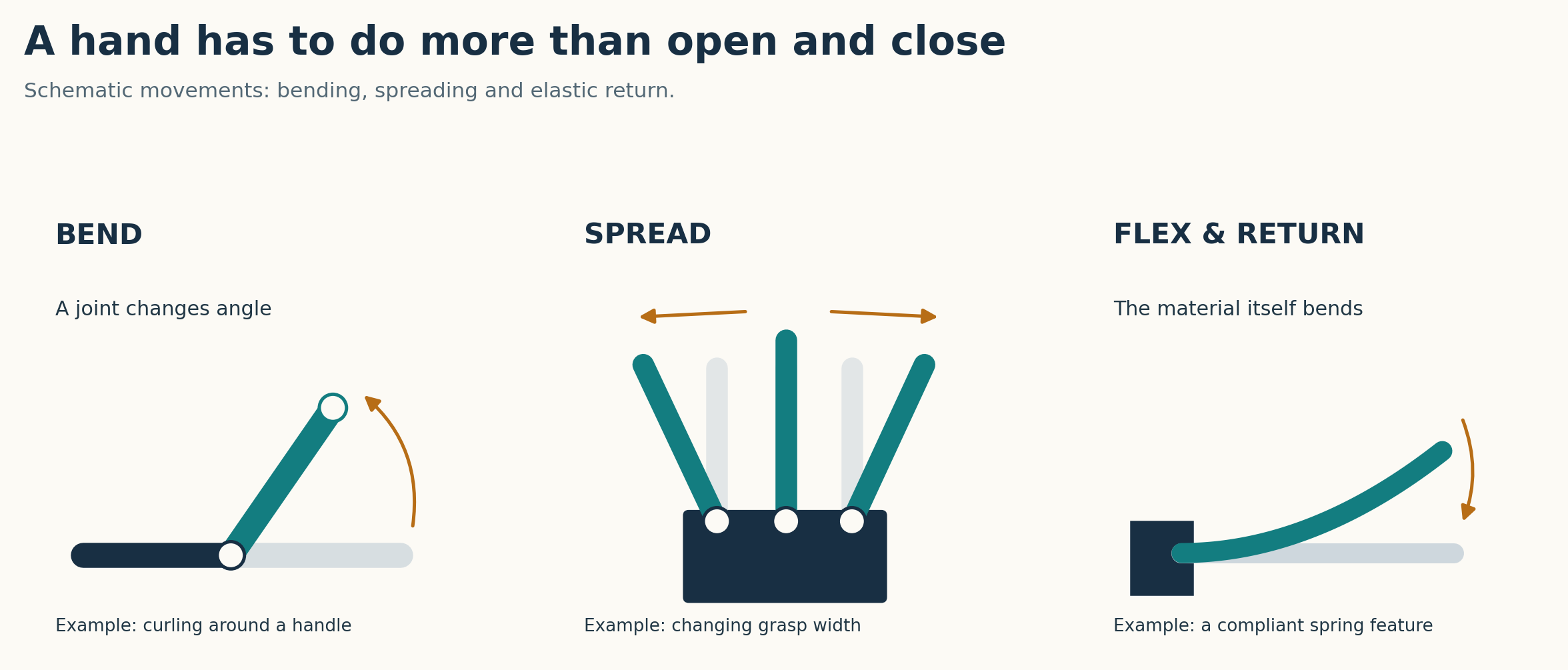
Small details matter. Pins must line up with holes. Tight fits can restrict movement; loose fits can introduce play. Manufacturing variations can accumulate across several joints. Cables need clearance, and worn components need to be accessible for replacement. Some contact is intentional: a flexible latch may bend against another part and spring back.
Why the economics matter
Production ambitions make those details worth studying. Hyundai announced plans in January 2026 for capacity of 30,000 robots a year by 2028. That is a target, not delivered production.
A hypothetical program producing 100,000 two-handed robots would need 200,000 hands. Separately, a fleet with 200,000 hands would need 20,000 replacements annually if 10% were replaced each year. That replacement rate is an assumption; actual servicing may replace only a finger, tendon or sensor.
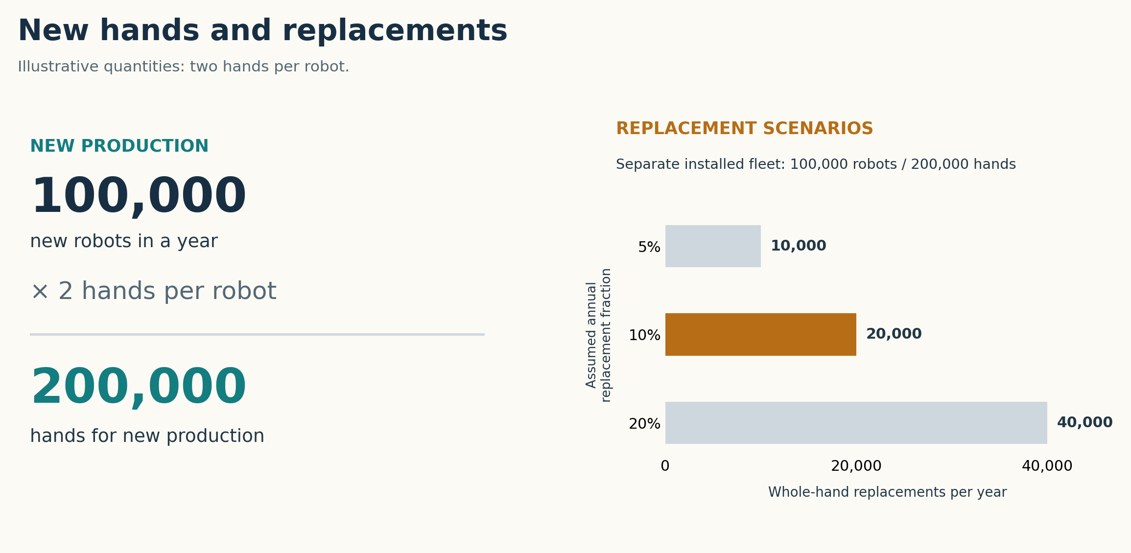
A single design can reach many manufactured units. Better placement tools could speed design review, compare variants and expose problems before production. Cost savings were not measured.
The first results
The initial case uses Pollen Robotics' four-fingered Amazing Hand. The kit contains 29 component designs used 226 times. Models must position those parts in CAD without altering their shapes or seeing the completed reference assembly.
The target budget was 30 minutes and 100 calls to execution tools; Grok's limits were operator-supervised. Time, tool-call and reasoning budgets were deliberately constrained to limit token use. Astra ran at Low (Lite), Medium and Extra high; Ultra was not tested. These results describe performance within those budgets. No higher-budget comparison establishes how much the limits affected the scores.
The score counts placements matching one reference pose within a nominal 0.1 mm threshold. The known-correct control matched 226/226.
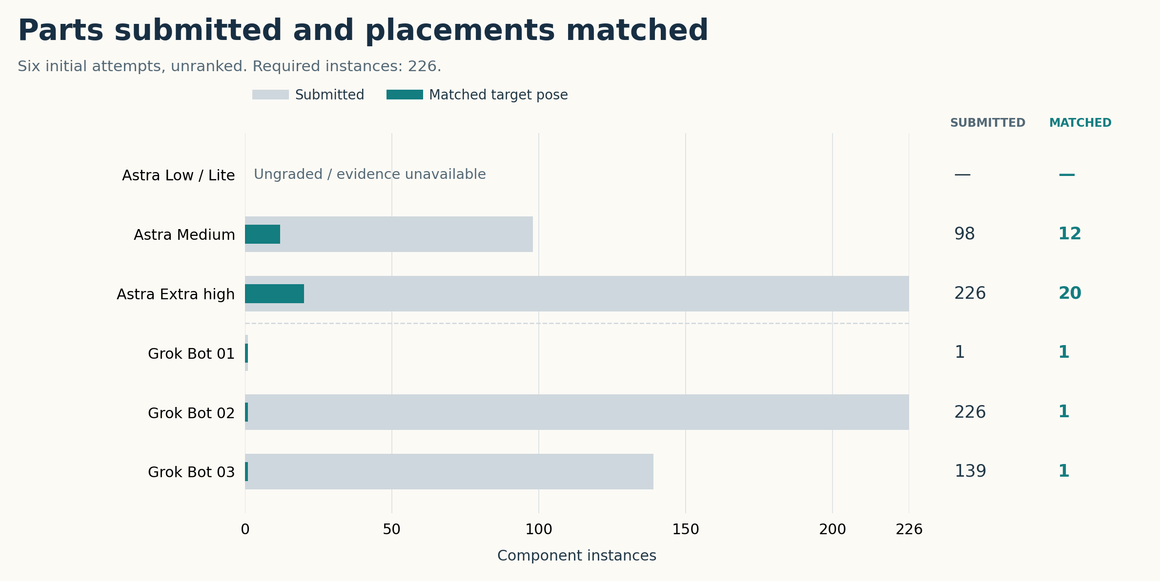
Across all three Grok runs, the sole match was the alignment reference. No other placement matched the reference. Astra Low remains ungraded because its execution evidence was incomplete. Every attempt is retained; none was replaced.
These are baseline observations, not a model ranking. All three Astra attempts timed out, their run-control software differed, and Medium retains a tool-call accounting qualification. Grok's underlying model version was unavailable and its activity records incomplete. A different, mechanically plausible hand pose can also miss this snapshot's target.
The score measures geometry and placement. STEP export checks are separate; future cases can use any format that preserves the required information.
From placement to optimization
Reliable placement could support an automated engineering loop: adjust an allowed position, check movement and clearance, simulate the loads, and compare the result.
Finite element analysis (FEA) divides a digital part into small elements to estimate how it bends and carries force. With suitable materials, loads and contact definitions, it could help compare joint settings or mounting positions while preserving design constraints.
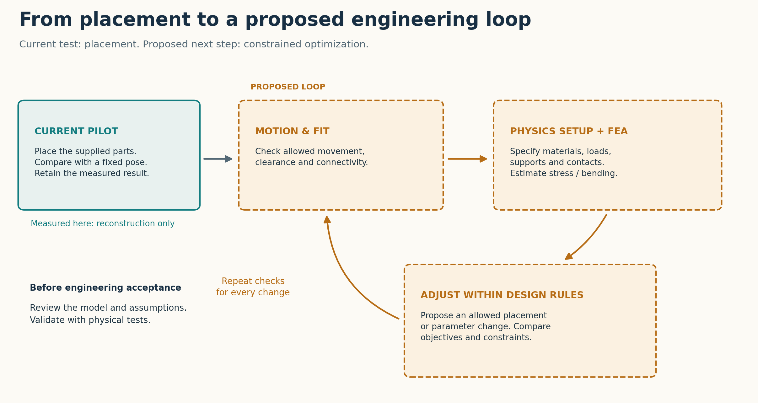
This loop is future work. The current pilot measures reconstruction, not optimized performance. Later candidates would face the same tasks and loading conditions, followed by engineering review and physical validation.
Keep the task and scoring fixed, and the next comparison can answer a useful question: how much better did the systems get?
The study began with an additional usage-reset credit from OpenAI. Building the benchmark consumed the renewed weekly allowance in roughly a day. That was a substantial investment in time and compute. The aim is to make that work useful to others.